V1 PROVED THE IDEA.
The first system proved the basic irrigation concept and brought its practical requirements into view.
PROJECT 01 / ENGINEERING CASE STUDY
An iterative redesign of an automated indoor growing system, bringing mechanical design, additive manufacturing, electronics and controlled irrigation into one physical system.
EXPLORE THE ENGINEERING ↓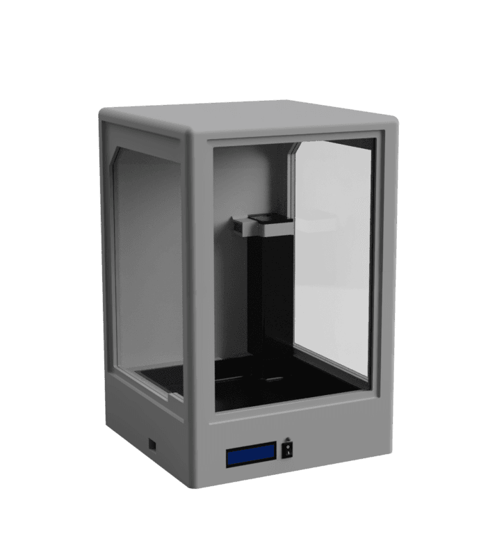
01 / BUILD EVIDENCE
A timelapse of the 3D printer making parts for the V2 assembly.
02 / ENGINEERING OVERVIEW
Follow the design from the frame and water path through to control and manufacture.
Eight designed frame pieces, three windows, a removable tray, tank and a servo-actuated hinged lid.
EXPLORE MECHANICAL DESIGN ↘A dedicated irrigation ring developed through practical testing of outlet size and water distribution.
EXPLORE WATER & IRRIGATION ↘Arduino-based sensing and control brings the pump, display, servo and grow lights into the system.
EXPLORE ELECTRONICS & CONTROL ↘Print constraints, material choices and physical testing informed successive design changes.
EXPLORE MANUFACTURING & ITERATION ↘03 / V1 → V2
V1 was a legitimate first prototype. Building it exposed specific limits that gave the redesign somewhere concrete to start.
The first system proved the basic irrigation concept and brought its practical requirements into view.
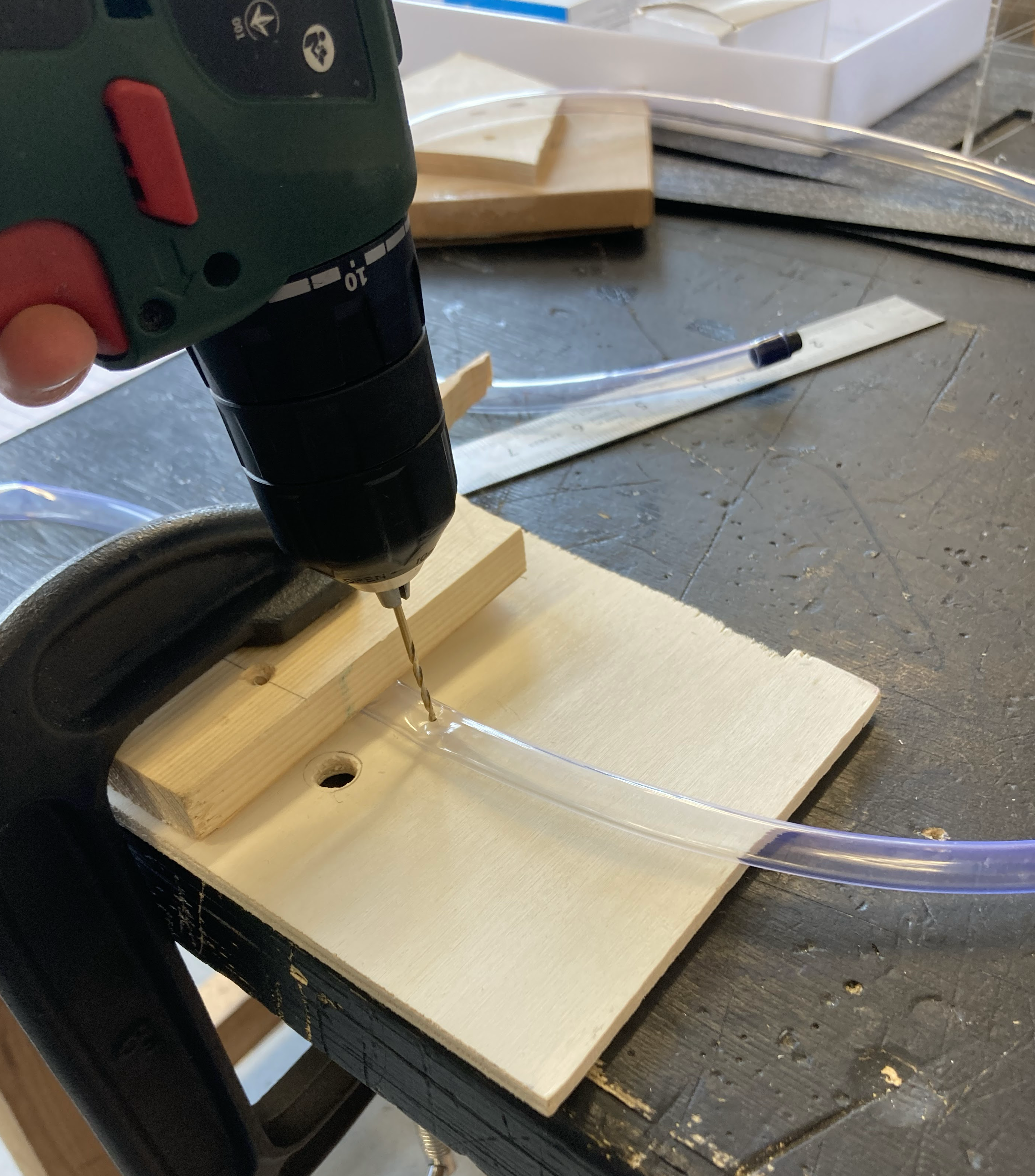
Holes drilled directly into PVC gave inconsistent outlet behaviour. V1 also had less integrated functionality than the later system.
The next design needed a more considered distribution method and closer integration of the mechanical, water and electronic systems.
V2 introduced a dedicated irrigation ring and brought the frame, tank, tray, electronics and control into one developed assembly.
04 / MECHANICAL DESIGN
The mechanical architecture was substantially redesigned in Fusion 360. The frame, windows, removable plant tray, water tank and irrigation system were developed as connected parts of one assembly.
The tank uses a custom 3D-printed hinged lid actuated by an SG90 micro servo. The hinge and lid were designed as part of the manufactured system and integrated with the Arduino control.
Due to the large size of the planter and the limitations of the 3D printer, the frame was split into 8 main pieces. As this allowed each piece to fit onto the print bed comfortably and not sacrifice quality.
Individually designed frame pieces
Windows in the frame
Removable plant tray
SG90 servo-actuated, 3D-printed tank lid and hinge
PHYSICAL ARCHITECTURE
This simplified exploded view focuses on the main frame, plant tray, water tank and irrigation ring. Electronics, lighting and smaller hardware are intentionally omitted so the mechanical architecture remains easy to understand.
05 / WATER & IRRIGATION
The irrigation ring changed through practical tests of outlet behaviour, pump characteristics and the water pattern reaching the planter.
Initial testing involved drilling outlets directly into the PVC pipe. While simple to manufacture, this approach produced uneven water distribution and inconsistent outlet behaviour. It was functional for initial testing, but small differences in drilling angle and hole diameter could affect the flow rate and direction between outlets. This choice made human error common and made the system difficult to reproduce consistently.
The first ring diameter and outlet holes were too large this caused the water to form large droplets and caused outlet pressure to be reduced.
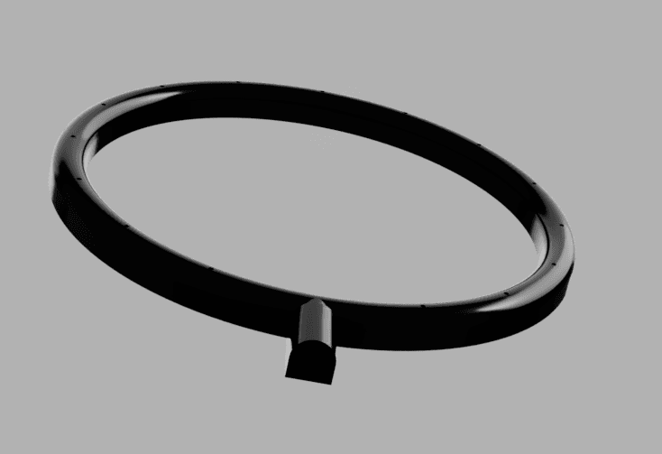
A dedicated irrigation ring, 3D-printed in black PETG with 16 × 1.5 mm outlets. Practical testing and the pump flow characteristics informed the decision to reduce the outlet sizing, producing a more even, fine rain effect.
Outlet sizing was selected through practical testing and by considering the pump flow and a feasible total outlet area; no CFD result is claimed.
The water tank required several iterations before a reliable, watertight design was achieved. Each prototype exposed a different limitation in either manufacturing, material selection or geometry.
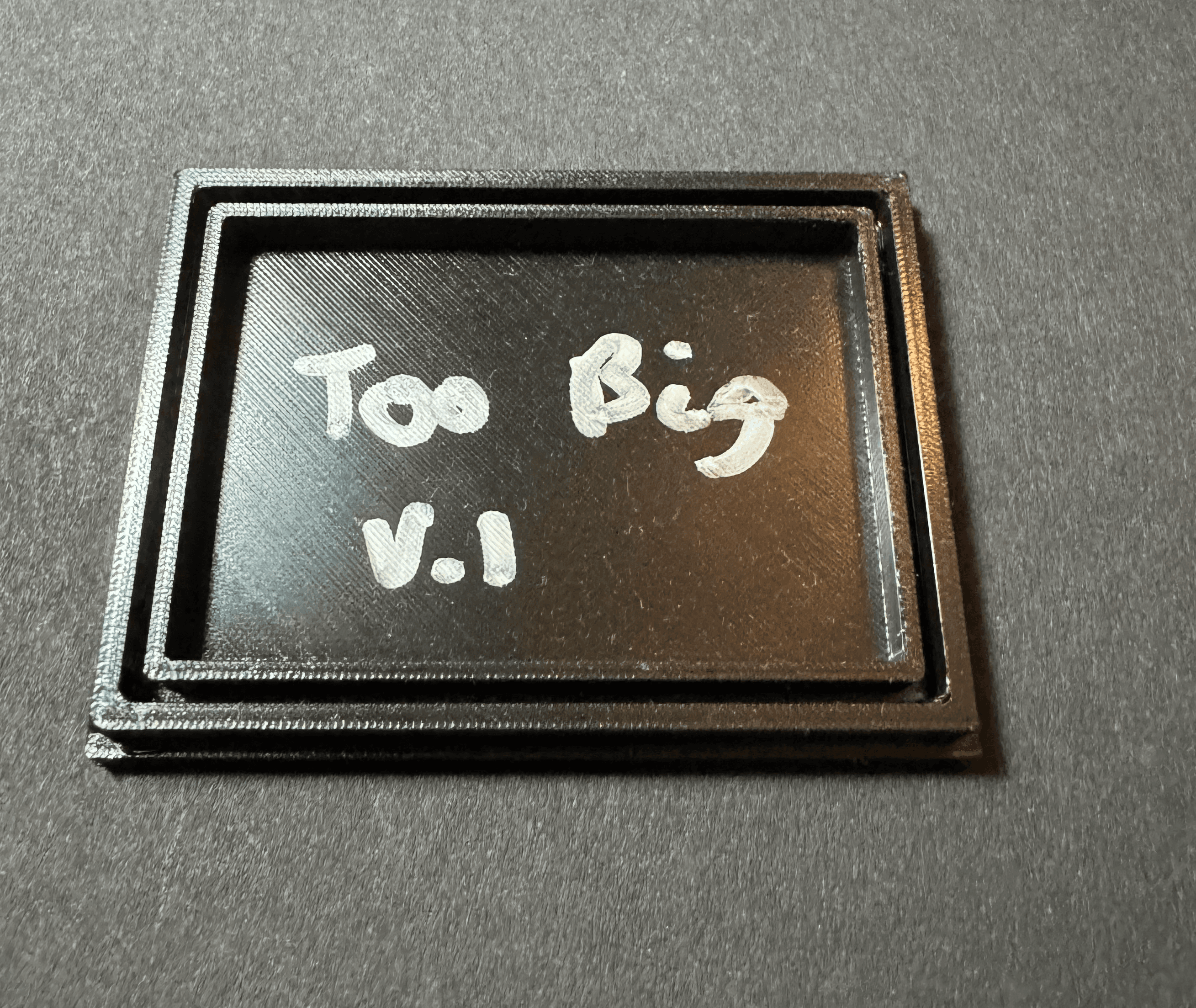
The first lid design used very tight tolerances, but the resulting fit was too restrictive for reliable assembly.
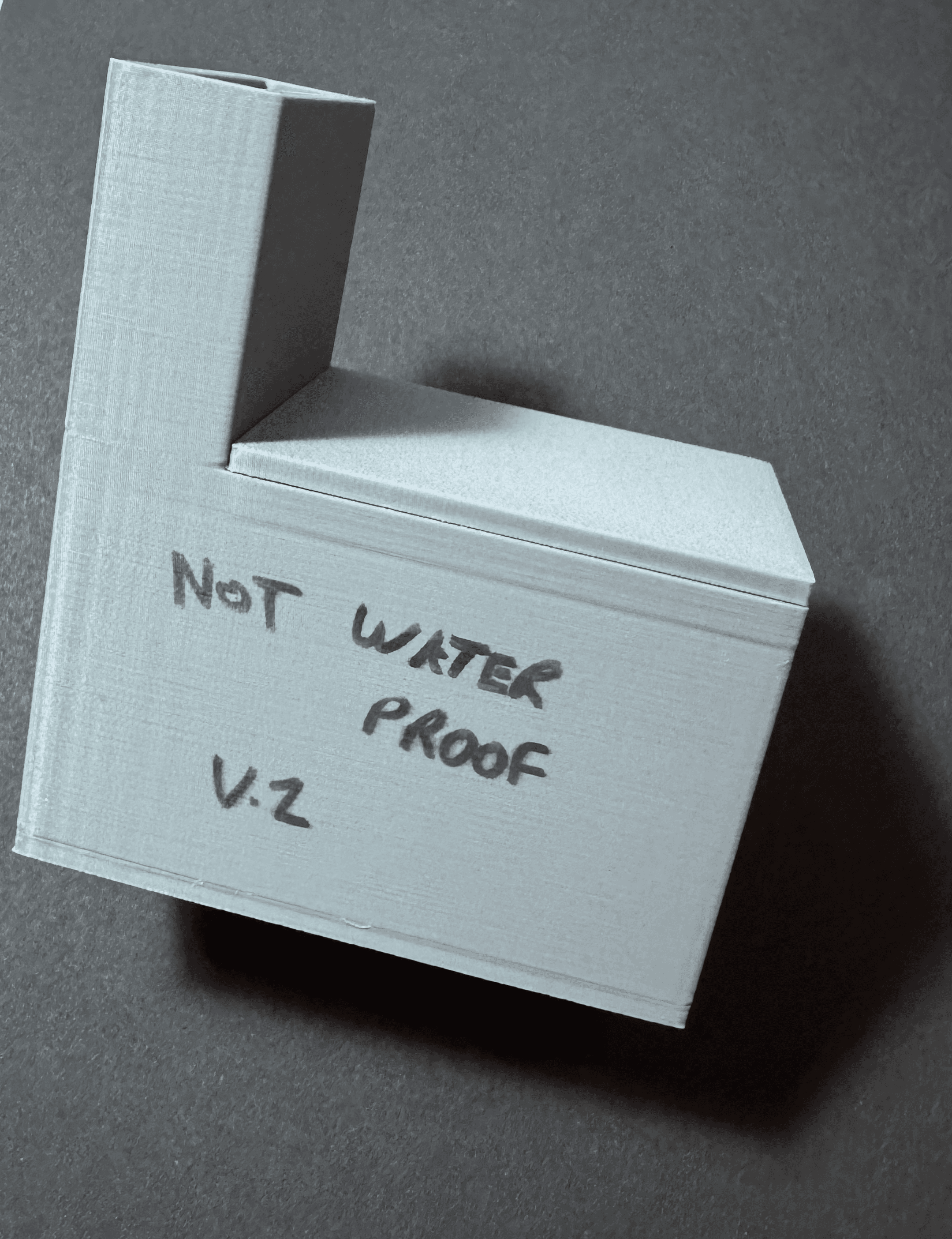
Printed in PLA, the tank was unable to reliably retain water due to small gaps within the FDM print structure.
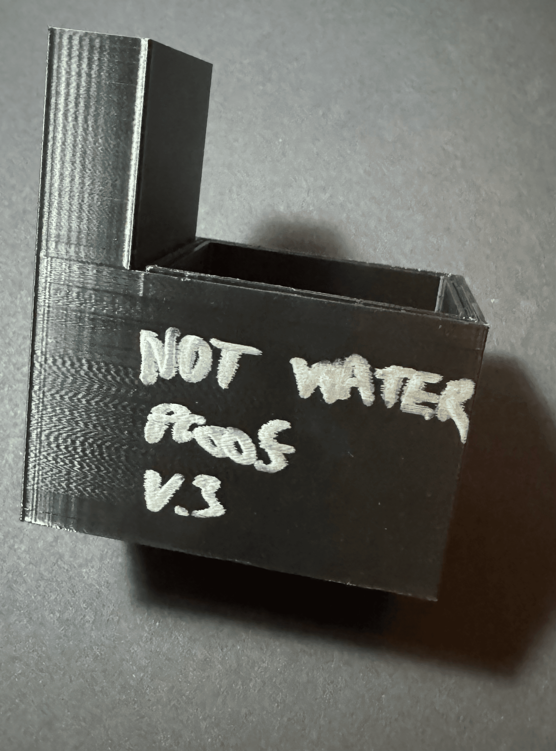
PETG improved water retention, but the geometry required the lid to sit below the maximum water level, making leakage unavoidable regardless of the tolerances.
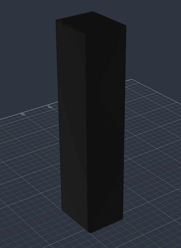
After several iterations, the design was simplified into a more traditional, robust geometry. This allowed the tank to be manufactured reliably while maintaining water retention and providing practical access to the lid. Additionally this design allowed for a larger total volume of 450 mL which would allow for longer periods of time between refills.
06 / ELECTRONICS & CONTROL
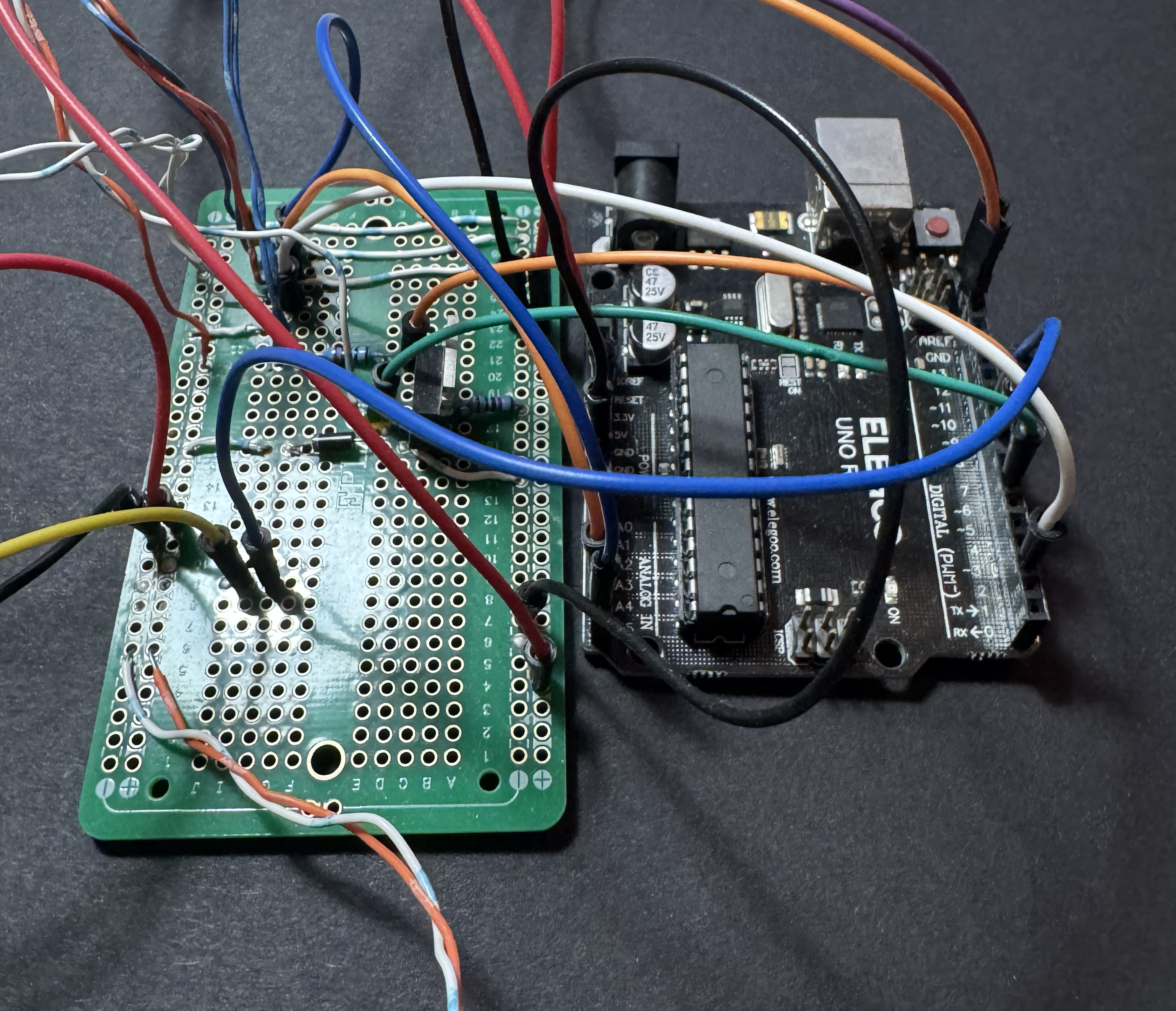
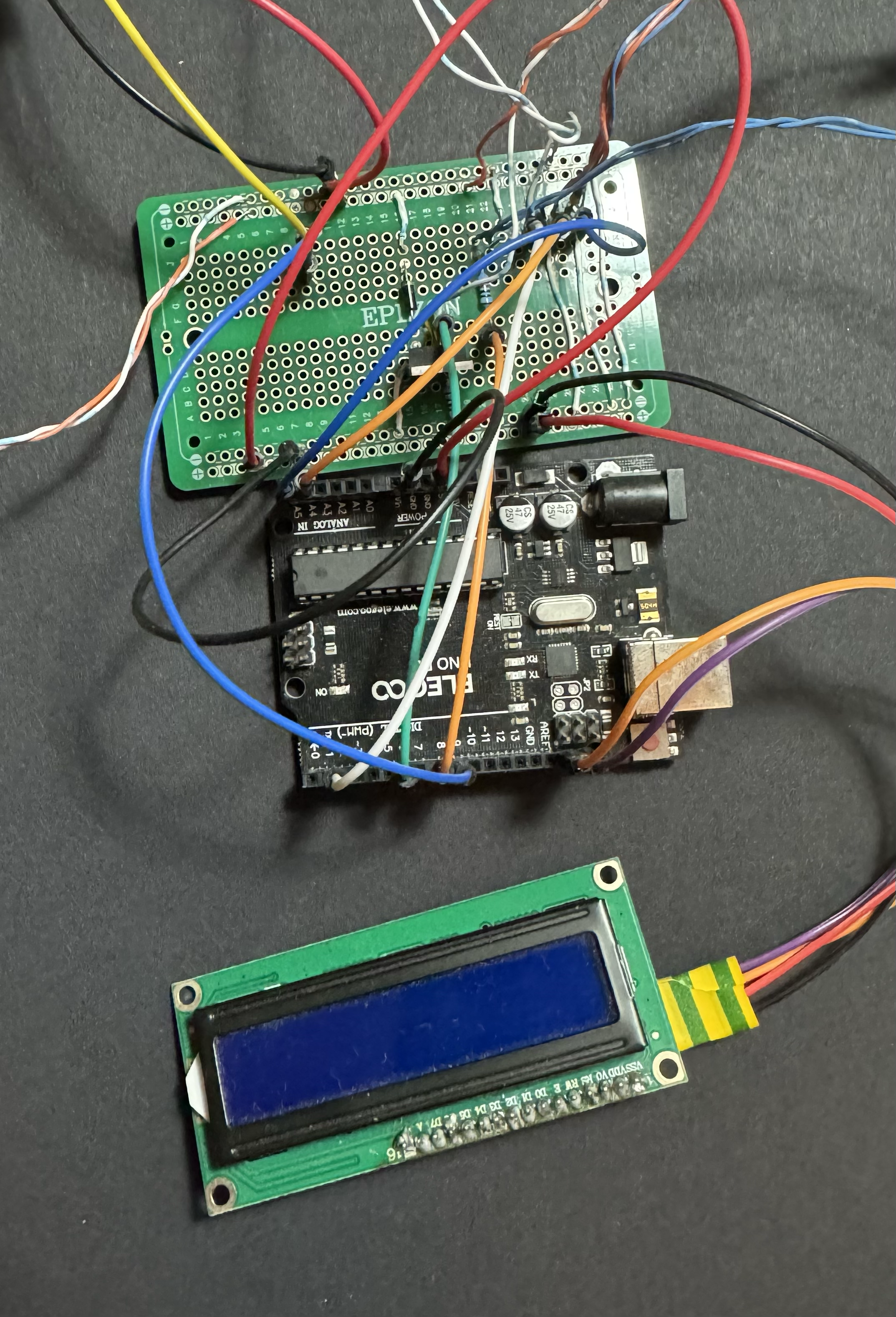
An Arduino Uno R3 is the central controller. A shared 5 V USB supply feeds a custom stripboard power-distribution rail that organises power delivery to the system.
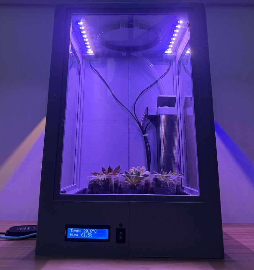
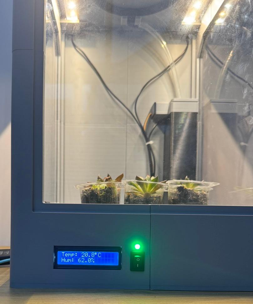
The Arduino switches the pump through an IRLZ34N N-channel MOSFET rather than powering it from a GPIO pin, a flyback diode across the pump provides inductive voltage protection. An AHT20 measures temperature and relative humidity, and a BMP280 measures barometric pressure and temperature; the readings are then displayed on the LCD. A SG90 micro servo actuates the tank lid, and a physical switch activates the pump manually with a green LED indicating when the pump is in auto mode.
Arduino Uno R3 / physical pump switch
5 V USB supply / custom stripboard rail
AHT20 temperature & relative humidity / BMP280 barometric pressure & temperature / environmental LCD readout
SG90 tank-lid servo / DC pump / two grow-light strips
IRLZ34N N-channel MOSFET / flyback diode
THREE LIGHTING MODES
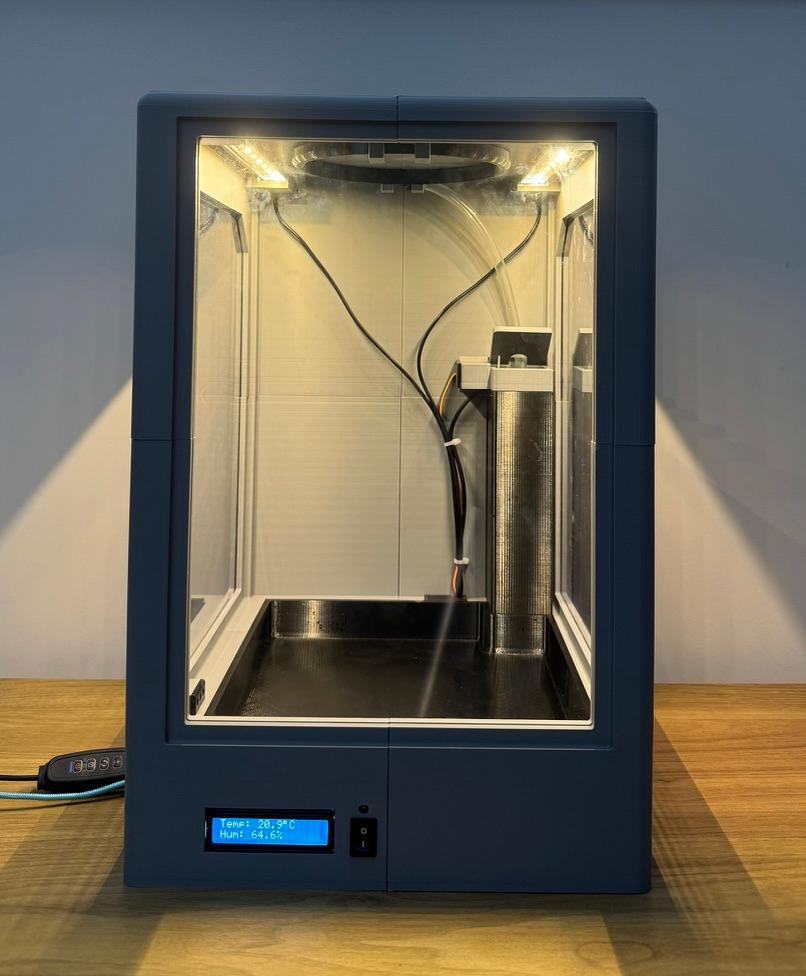
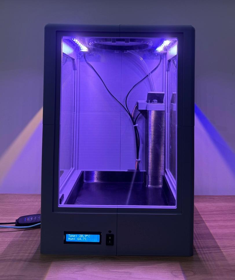
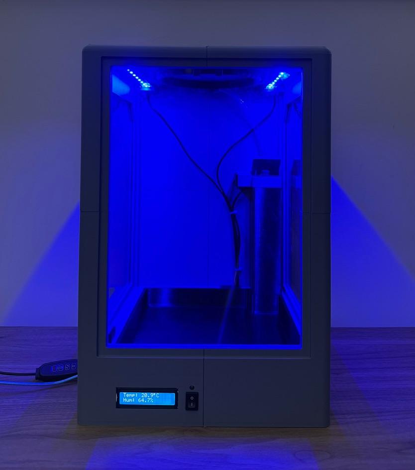
Different lighting modes create distinct visual conditions within the planter. The benefits of these modes for plant growth are that they can promote seed rooting and germination, enhance photosynthesis and promote accelerated plant growth.
07 / MANUFACTURING & ITERATION
Material and geometry decisions had to account for how each part would be made and used in the physical assembly.
Used for structural components where appropriate due to the cost per Kg being less than PETG. As well as PLA being quicker and easier to print which was important when printing pieces that take more than 10 hours.
Selected where water resistance and reduced leakage risk were important because of its better layer adhesion and lower water absorption than PLA.
08 / SYSTEM ARCHITECTURE
The control signal and pump power path are separate parts of the same 5 V system.
AHT20 + BMP280 sensors · LCD · manual switch · SG90 servo
Control signal to MOSFET gateIRLZ34N switches pump power from the rail.
Flyback diode across the pumpPart of the integrated 5 V system.
09 / TESTING & VALIDATION
Physical checks confirmed the key watering, sealing and lid actuation functions on the assembled prototype.
≈ 50 mL delivered per cycle, with very consistent results ± 2 mL over 10 cycles.
Estimated from the repeated three-second delivery testing over a 72-hour period. This corresponds to roughly 50 mL per 3-second cycle.
No leakage was observed from water-contact components during testing.
The lid opened and closed reliably, and the complete assembled prototype operated as a functioning system.
The 200 L/h figure is the pump's free-flow rating with no restriction. In the system, water passes through the feed tubing and sixteen 1.5 mm outlets, which restrict flow, so the delivered rate is lower.
10 / FINAL PHYSICAL PROTOTYPE
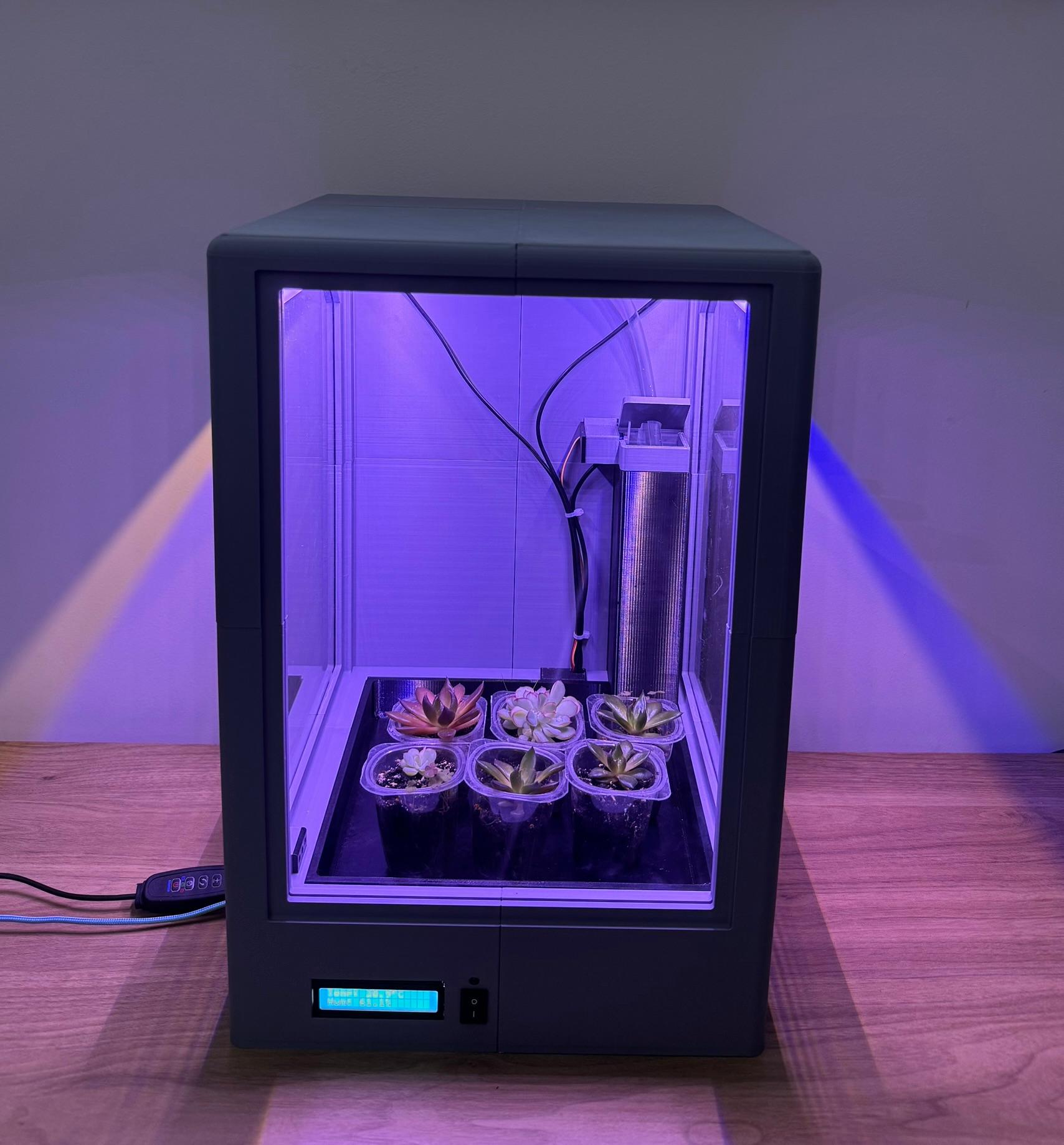
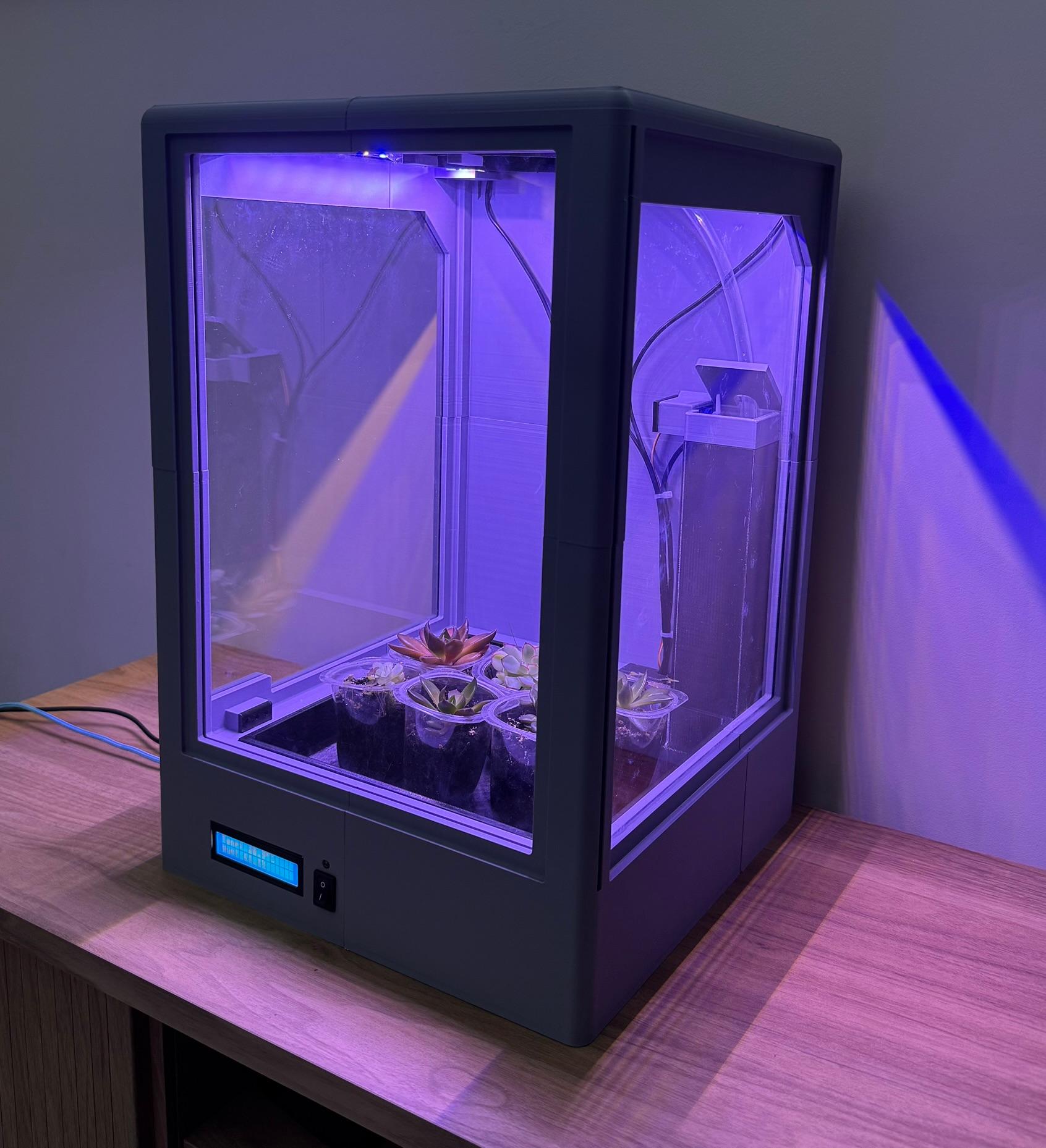
Planter V2 brings the frame, removable tray, tank, irrigation ring, sensing, control and lighting into one physical build. This is the manufactured and assembled prototype, a complete system whose key functions were tested in operation.
11 / NEXT ITERATION
V2 addresses the main limitations identified in the first build, and physical testing validated its key functions. The remaining opportunities are mainly usability, mechanical refinement and a more capable user interface.
V3 / FUTURE USER INTERFACE
A touchscreen could add on-device watering presets, duration and frequency settings, and saved programs. This is a future development direction, not a V2 feature; changing the current program still requires uploading another Arduino program from a laptop.