02 / SMART IRRIGATION SYSTEM
V1 —
FIRST
ITERATION.
The first generation of the smart irrigation system, built to explore the concept and discover what the system actually needed.
01 / THE IDEA
START
WITH A
SIMPLE
PROBLEM.
The project began with a simple question: could a plant be watered automatically without relying on someone to remember to do it?
V1 was the first attempt to turn that idea into a working physical system. Rather than designing the final product immediately, the goal was to build something that could prove the concept and reveal the practical challenges involved.
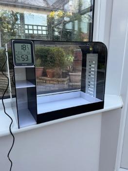
This first iteration combined a laser-cut acrylic body, a 3D-printed water tank and electronics into a single working prototype, with manual pump control and a temperature and humidity display.
02 / PROTOTYPING
FROM SKETCH TO CAD.
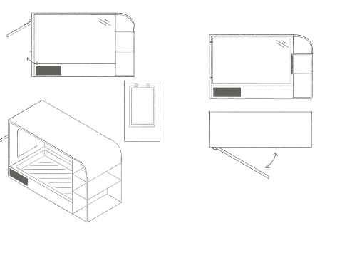
Early sketches were used to explore the overall form, layout and functionality of the product before committing to a final CAD design.
03 / FINAL DESIGN
REFINED IN CAD.
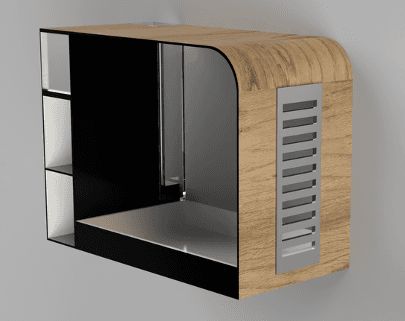
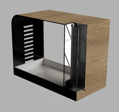
The CAD renders show the intended final appearance, including a wood veneer. The veneer was ultimately omitted from the manufactured prototype due to its additional cost.
04 / BUILD & TESTING
FROM CAD TO
A REAL SYSTEM.
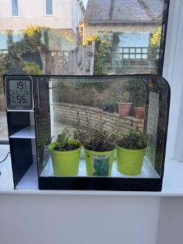
The first prototype brought the mechanical structure, water delivery system and manual pump control together in a physical product. Building it made it possible to see how the design behaved beyond the CAD model.
Testing exposed practical limitations. The acrylic construction made the system heavier and more fragile than intended, while reliable waterproof joints were difficult to achieve with the laser-cut components.
05 / V1 → V2
V1 →
V2.
V1 proved that the concept could work, but the prototype also revealed where the original approach was holding the system back.
The next step was not simply to repair those weaknesses. It was to reconsider the construction, integration and manufacturing of the entire system.
PROVE THE CONCEPT.
The first physical prototype established that the idea could be built and exposed practical limits. The acrylic body made the system heavier and more fragile than intended, and reliable waterproof joints were difficult to make with laser-cut parts.
RETHINK THE SYSTEM.
Those findings informed a redesigned approach to construction, integration and manufacturing. V2 brought the frame, tank, tray, irrigation and electronics together as a developed assembly. V1's pump was switched manually; V2 introduced automated, timed watering controlled by the Arduino.
06 / RESULT
THE FIRST
STEP.
V1 turned the original idea into a working physical prototype and established the practical requirements that shaped the next iteration.
EXPLORE V2